- 您现在的位置:买卖IC网 > Sheet目录344 > MSC8144ADS (Freescale Semiconductor)ADS FOR MSC8144 DEVICE
Electrical Characteristics
2.6.5.6
Receiver Eye Diagrams
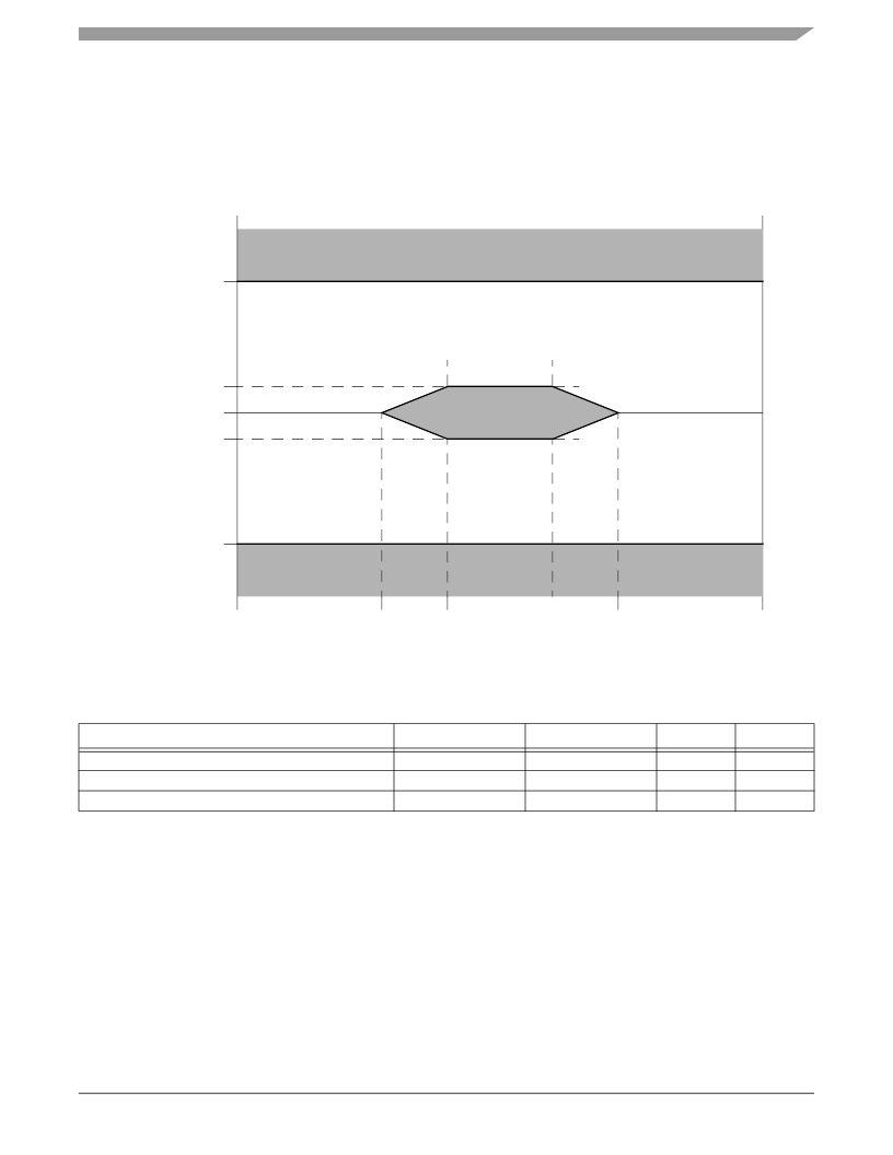
For each baud rate at which an LP-Serial receiver is specified to operate, the receiver shall meet the corresponding bit error rate
specification ( Table 32 , Table 33 , and Table 34 ) when the eye pattern of the receiver test signal (exclusive of sinusoidal jitter)
falls entirely within the unshaded portion of the receiver input compliance mask shown in Figure 14 with the parameters
specified in Table 35 . The eye pattern of the receiver test signal is measured at the input pins of the receiving device with the
device replaced with a 100 Ω ± 5% differential resistive load.
V DIFF max
V DIFF min
0
–V DIFF min
–V DIFF max
0
A
B
1–B
1–A
1
Time (UI)
Figure 14. Receiver Input Compliance Mask
Table 35. Receiver Input Compliance Mask Parameters Exclusive of Sinusoidal Jitter
1.25 GBaud
2.5 GBaud
3.125 GBaud
Receiver Type
V DIFF min (mV)
100
100
100
V DIFF max (mV)
800
800
800
A (UI)
0.275
0.275
0.275
B (UI)
0.400
0.400
0.400
2.6.5.7
Measurement and Test Requirements
Since the LP-Serial electrical specification are guided by the XAUI electrical interface specified in Clause 47 of IEEE Std.
802.3ae-2002?, the measurement and test requirements defined here are similarly guided by Clause 47. In addition, the CJPAT
test pattern defined in Annex 48A of IEEE Std. 802.3ae-2002 is specified as the test pattern for use in eye pattern and jitter
measurements. Annex 48B of IEEE Std. 802.3ae-2002 is recommended as a reference for additional information on jitter test
methods.
MSC8144 Quad Core Digital Signal Processor Data Sheet, Rev. 16
Freescale Semiconductor
49
发布紧急采购,3分钟左右您将得到回复。
相关PDF资料
MSC8156EVM
EVAL MODULE FOR MSC8156 LC
MSL1060AW
IC LED DRIVER 6 STRING
MSL1061AV
IC LED DRIVER 6 STRING
MSL2041GU
IC LED DRIVER 4 STRING
MSL2100BR
IC LED DRIVER 8 STRING
MSL2160DQ
IC LED DRIVER 16 STRING
MSL2162DQ
IC LED DRIVER 16 STRING
MSL3082CS
IC LED DRIVER 8 STRING
相关代理商/技术参数
MSC8144AMC-SA
制造商:Freescale Semiconductor 功能描述:BOARD AMC SGL WIDTH MSC8144 DSP
MSC8144E
制造商:FREESCALE 制造商全称:Freescale Semiconductor, Inc 功能描述:Quad Core Digital Signal Processor
MSC8144EC
制造商:FREESCALE 制造商全称:Freescale Semiconductor, Inc 功能描述:Quad Core Digital Signal Processor
MSC8144ESVT1000B
制造商:Freescale Semiconductor 功能描述:DSP 32-BIT 1GHZ 1000MIPS 783-PIN FCBGA BOX - Trays 制造商:Freescale Semiconductor 功能描述:ENCRYPTION PACSUN R2.1 783FCPBGA
MSC8144ESVT800A
制造商:Freescale Semiconductor 功能描述:DSP 32BIT 800MHZ 800MIPS 783FCBGA - Trays
MSC8144ESVT800B
制造商:Freescale Semiconductor 功能描述:DSP 32-BIT 800MHZ 800MIPS 783-PIN FCBGA EACH - Bulk 制造商:Freescale Semiconductor 功能描述:ENCRYPTION PACSUN R2.1 783FCPBGA
MSC8144ETVT1000A
制造商:Freescale Semiconductor 功能描述:DSP 32-BIT 1GHZ 1000MIPS 783-PIN FCBGA - Bulk
MSC8144ETVT1000B
制造商:Freescale Semiconductor 功能描述:DSP 32-BIT 1GHZ 1000MIPS 783-PIN FCBGA EACH - Bulk 制造商:Freescale Semiconductor 功能描述:ENCRYPTION PACSUN R2.1 783FCPBGA
